Introduction
In 2026, 3D CAD (Computer-Aided Design) software continues to play an important role in engineering, manufacturing, automotive, aerospace, architecture, and product design. These tools help professionals create accurate three-dimensional models, technical drawings, mechanical assemblies, and detailed product designs. They also help engineers test ideas, identify design problems, and improve products before manufacturing.
Traditional design methods often require physical prototypes to check whether a product will work correctly. This can take time and increase development costs. With 3D CAD software, designers can create digital models and make changes before producing physical components. They can check dimensions, examine individual parts, study assemblies, and prepare technical documents using the same digital design.
Modern 3D CAD applications offer much more than basic modeling. Many include parametric design, surface modeling, sheet metal tools, simulation, rendering, manufacturing preparation, and cloud collaboration. Some platforms also connect computer-aided design with computer-aided manufacturing (CAM) and computer-aided engineering (CAE).
Choosing the right 3D CAD software is important for both beginners and experienced professionals. Each application has different strengths. Some are designed for mechanical engineering, while others focus on product development, complex surfaces, large assemblies, or advanced manufacturing.
The right choice depends on your industry, project requirements, budget, technical skills, computer specifications, and collaboration needs. For example, a student learning mechanical design may prefer FreeCAD or Autodesk Fusion. A company designing complex aircraft components may need CATIA or Siemens NX.
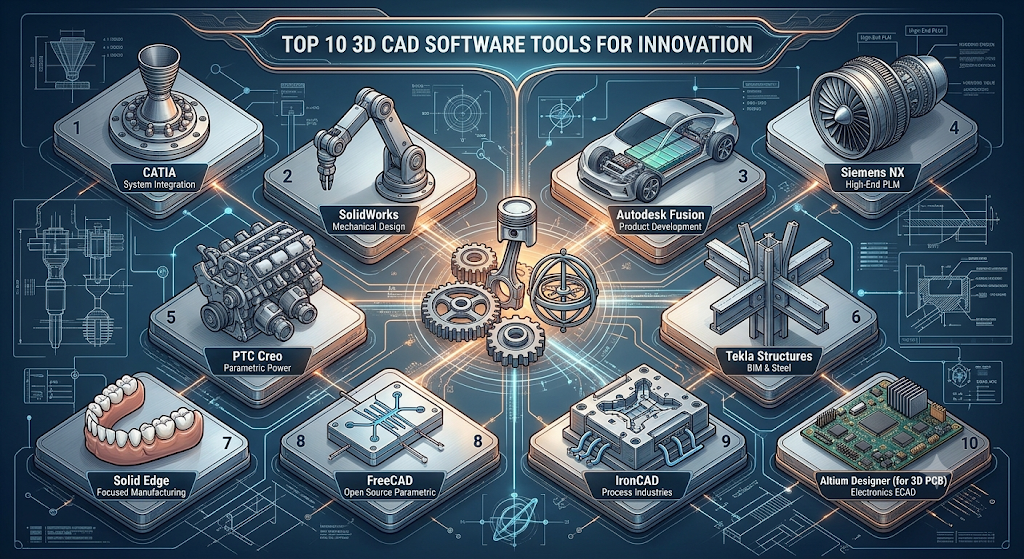
This blog explores the top 10 3D CAD software tools in 2026. It explains what each tool does, its major features, practical benefits, limitations, and common use cases. You will also find comparison tables, selection guidance, a practical design workflow, and frequently asked questions.
What Is 3D CAD Software?
3D CAD software is a computer application used to create, modify, examine, and document three-dimensional designs. CAD stands for Computer-Aided Design. Engineers, architects, manufacturers, and product designers use these applications to develop digital models before making physical products.
A 3D model represents an object using three dimensions: length, width, and height. Users can rotate the model, zoom in on individual features, examine its geometry, and view it from different angles.
For example, a mechanical engineer can use 3D CAD software to design a machine component. The engineer can define its dimensions, add holes, create curved surfaces, and combine it with other components to form a complete assembly.
3D CAD software also helps teams make design changes more efficiently. Instead of rebuilding an entire model, users can edit selected dimensions, features, or components. In parametric applications, related features can update when the original design parameters change.
Common applications of 3D CAD software include:
- Mechanical Engineering: Designing machine parts, gears, shafts, brackets, tools, and mechanical assemblies.
- Product Design: Developing consumer products, electronic devices, furniture, appliances, and industrial equipment.
- Automotive Engineering: Designing vehicle components, body structures, engine parts, and mechanical systems.
- Aerospace Engineering: Creating aircraft components, structural parts, and complex engineering assemblies.
- Architecture: Developing building components, structural models, and architectural concepts.
- Manufacturing: Preparing product designs for CNC machining, sheet metal fabrication, and production.
- 3D Printing: Creating digital models that can be exported for additive manufacturing.
- Industrial Design: Developing products with customized shapes, smooth surfaces, and functional details.
Top 10 3D CAD Software Tools in 2026
1. Autodesk Fusion
Short Description:
Autodesk Fusion is a cloud-connected product design and engineering platform developed by Autodesk. It combines 3D CAD, CAM, and CAE capabilities in one environment. This allows users to design products, prepare manufacturing operations, and perform selected engineering analyses within a connected workflow.
Autodesk Fusion is widely used by mechanical engineers, product designers, manufacturers, students, and small businesses. It supports the development of individual components as well as complete product assemblies. Users can create solid models, surface designs, mesh geometry, and freeform shapes depending on their project requirements.
One of its main advantages is the connection between product design and manufacturing. A designer can create a mechanical component and then prepare it for CNC machining without moving the entire project into a separate design environment. This can reduce repeated file transfers and make design changes easier to manage.
Fusion also supports cloud-connected collaboration. Users can share design data and work with other team members. This is useful for small businesses and product development teams that need to manage design information across different locations.
Key Features:
– 3D Modeling: Autodesk Fusion supports solid, surface, mesh, and freeform modeling. Users can create mechanical parts, product housings, brackets, enclosures, and other components. Different modeling methods provide flexibility for both engineering designs and more complex shapes.
– Parametric Design: Users can create models using sketches, dimensions, constraints, and design features. When a parameter changes, connected features can update according to the model’s design history. This is helpful when developing multiple versions of the same product.
– Assembly Design: Fusion allows users to combine individual components into a larger product assembly. Designers can define component relationships and examine how parts fit together. This helps identify possible interference or alignment issues during the design process.
– Simulation Tools: Available simulation capabilities help users examine selected engineering conditions. Depending on the available tools and license, designers can study structural behavior, thermal conditions, and other performance factors.
– CAM Integration: The manufacturing environment helps users prepare models for CNC machining. It supports machining operations, toolpath planning, and manufacturing setup. This reduces the need to transfer designs between unrelated applications.
– Cloud Collaboration: Design data can be stored and shared through Autodesk’s connected platform. Team members can access project information and collaborate using supported permissions and workflows.
– Generative Design: Generative design tools can explore alternative shapes based on selected design goals and constraints. This helps engineers investigate different design solutions rather than relying only on manual modeling.
– 3D Printing Support: Users can prepare models for additive manufacturing and export supported file formats. This is useful for prototypes, product testing, and customized components.
Benefits:
- Combines design and manufacturing capabilities in one platform.
- Helps reduce repeated work between CAD and CAM processes.
- Supports product development from concept to prototype.
- Provides modeling options for different design requirements.
- Offers collaboration features for distributed teams.
- Suitable for small businesses that need several engineering tools.
- Supports CNC machining and 3D printing workflows.
Pros:
- Combines CAD, CAM, and CAE capabilities.
- Suitable for product design and prototyping.
- Offers a connected design and manufacturing workflow.
- Provides tools for beginners and experienced users.
- Supports cloud-based collaboration.
- Includes useful learning resources and tutorials.
Cons:
- Some advanced features require paid plans.
- Cloud-connected workflows depend on internet availability for certain functions.
- Complex projects may require powerful hardware.
- Users need time to understand advanced simulation and manufacturing tools.
- Available capabilities can differ between subscription plans.
Use Cases:
- Mechanical Component Design: Creating brackets, shafts, machine parts, and mechanical fittings.
- Product Prototyping: Developing product concepts and preparing them for physical testing.
- CNC Machining: Creating toolpaths for machining components from metal, plastic, and other materials.
- 3D Printing: Preparing customized parts and prototype models.
- Small-Scale Manufacturing: Managing design and manufacturing tasks in one connected environment.
- Consumer Product Development: Designing housings, enclosures, accessories, and other manufactured products.
Best For:
- Mechanical engineers.
- Product designers.
- Students and educators.
- Small manufacturing businesses.
- 3D printing enthusiasts.
- CNC machining and prototyping projects.
2. SOLIDWORKS
Short Description:
SOLIDWORKS is a professional 3D CAD software developed by Dassault Systèmes. It is widely used in mechanical engineering, product development, manufacturing, industrial equipment design, and machine building.
The software is especially known for its parametric modeling capabilities. Users can create individual components using sketches and features, combine those components into assemblies, and generate detailed engineering drawings. Its feature-based modeling approach helps engineers understand how a design was created and modify it when requirements change.
SOLIDWORKS is useful for designing products that contain multiple mechanical parts. For example, an engineer can design a motor housing, mounting brackets, shafts, fasteners, and other components. These parts can then be combined into an assembly to check how they fit together.
The software also offers tools for sheet metal design, weldments, product documentation, and simulation through available products and licenses. These capabilities make it useful throughout many stages of mechanical product development.
Key Features:
– Parametric Modeling: Users create designs using sketches, dimensions, geometric relationships, and modeling features. The software maintains design relationships so that changes can update connected features. This is valuable when engineers need to produce several versions of a component.
– Part Design: SOLIDWORKS provides features such as extrusion, revolution, sweep, loft, fillet, chamfer, and hole creation. These tools help users build detailed mechanical components with accurate dimensions.
– Assembly Design: Individual parts can be combined into a complete product assembly. Mates define how components connect and move relative to each other. Engineers can use assemblies to check component positioning and identify potential interference.
– Sheet Metal Design: Dedicated tools help users create sheet metal components, bends, flanges, and flat patterns. These features are useful when designing enclosures, cabinets, machine covers, and fabricated metal products.
– Weldment Tools: Weldment functionality supports the design of structural frames using profiles and members. It is useful for machine frames, support structures, industrial platforms, and equipment stands.
– Simulation: Available simulation products can help engineers examine selected structural, thermal, and other engineering conditions. Simulation can support design evaluation before physical testing.
– Technical Drawings: SOLIDWORKS can generate 2D drawings from 3D models. Users can add dimensions, tolerances, annotations, sections, and other manufacturing details.
– Design Configurations: Configurations allow users to manage variations of a part or assembly in one document. This can help companies create products with different sizes or specifications.
– Design Automation: Reusable features, templates, configurations, and automation tools can reduce repetitive design work.
Benefits:
- Helps engineers create accurate mechanical components.
- Makes it easier to manage products containing multiple parts.
- Supports the preparation of manufacturing drawings.
- Reduces repeated modeling work through reusable features.
- Helps identify assembly and design issues before production.
- Supports sheet metal and structural frame development.
- Provides a familiar workflow for many mechanical engineering teams.
Pros:
- Widely used in mechanical engineering and manufacturing.
- Strong part and assembly modeling capabilities.
- Excellent tools for engineering drawings.
- Supports sheet metal and weldment design.
- Large user community and learning resources.
- Suitable for detailed product development.
Cons:
- Professional licenses can be expensive.
- Some advanced features require additional products or licenses.
- The standard desktop version requires a suitable Windows-based workstation.
- Complex assemblies can require significant computing resources.
- Advanced modeling and simulation require training.
Use Cases:
- Machine Design: Designing industrial machines, mechanical systems, and equipment.
- Automotive Components: Developing brackets, housings, mounting systems, and mechanical parts.
- Sheet Metal Products: Creating electrical cabinets, enclosures, panels, and machine covers.
- Industrial Equipment: Designing conveyors, frames, fixtures, and production equipment.
- Consumer Products: Developing appliances, tools, accessories, and mechanical products.
- Engineering Documentation: Preparing manufacturing drawings and assembly documentation.
Best For:
- Mechanical engineers.
- Product development teams.
- Manufacturing companies.
- Machine designers.
- Sheet metal designers.
- Engineering students.
3. Autodesk Inventor
Short Description:
Autodesk Inventor is a professional 3D mechanical design and engineering application developed by Autodesk. It is used to create accurate product models, mechanical assemblies, sheet metal components, and manufacturing drawings.
Inventor focuses on mechanical engineering workflows. Its parametric modeling environment allows users to develop parts using dimensions, sketches, and design features. These parts can be combined into larger assemblies to represent complete machines or products.
The software is particularly useful for industrial equipment, machinery, mechanical systems, and manufactured products. Engineers can use it to design components, examine assembly relationships, and prepare technical documentation.
Inventor also includes specialized tools for sheet metal, frame design, and automation. Its integration with other Autodesk applications supports organizations that already use Autodesk products for design and manufacturing.
Key Features:
– 3D Parametric Modeling: Inventor allows users to create parts using sketches, dimensions, constraints, and modeling features. Design changes can be managed through the model’s feature history.
– Assembly Modeling: Engineers can combine multiple parts into a complete product assembly. They can define component relationships, examine clearances, and check how different parts fit together.
– Sheet Metal Design: Dedicated tools help users create sheet metal parts, bends, flanges, and flat patterns. This supports the design of cabinets, enclosures, machine covers, and fabricated components.
– Frame Generator: This feature helps designers create structural frames using standard profiles. It can be used for equipment supports, machine frames, and industrial structures.
– Simulation Tools: Available simulation capabilities support the evaluation of selected engineering conditions. These tools can help identify areas that may need further design review.
– Drawing Generation: Inventor can create engineering drawings from 3D models. Users can add dimensions, annotations, section views, and other manufacturing information.
– iLogic Automation: iLogic allows users to automate design tasks and create rule-based models. This is useful when a company manufactures products with several sizes or configurations.
– Data Exchange: Inventor supports common engineering file formats and can work with other Autodesk applications. This helps teams share models with customers, suppliers, and manufacturing partners.
Benefits:
- Supports accurate mechanical product development.
- Makes it easier to manage assemblies and component relationships.
- Helps automate repetitive design tasks.
- Provides specialized tools for sheet metal and structural frames.
- Supports detailed engineering documentation.
- Integrates with other Autodesk design and manufacturing products.
- Useful for companies developing configurable mechanical products.
Pros:
- Powerful mechanical design capabilities.
- Suitable for complex assemblies and product structures.
- Supports detailed manufacturing documentation.
- Strong sheet metal and frame design tools.
- Integrates with other Autodesk products.
- Useful for industrial machinery and equipment design.
Cons:
- Advanced features require learning and practice.
- Subscription costs can be high.
- Large assemblies may require powerful hardware.
- Primarily focused on mechanical engineering workflows.
- Users may need additional tools for specialized design requirements.
Use Cases:
- Industrial Machinery: Designing machines, production equipment, and mechanical systems.
- Sheet Metal Manufacturing: Creating cabinets, panels, enclosures, and fabricated components.
- Structural Frame Design: Developing machine frames, support structures, and equipment stands.
- Product Engineering: Creating detailed product models and assemblies.
- Manufacturing Drawings: Preparing dimensions and documentation for production.
- Configurable Products: Creating product variations using automation and design rules.
Best For:
- Mechanical engineers.
- Industrial equipment designers.
- Manufacturing companies.
- Machinery design teams.
- Sheet metal designers.
- Product development professionals.
4. Onshape
Short Description:
Onshape is a cloud-native 3D CAD platform designed for product development and engineering teams. Unlike traditional desktop CAD applications, it allows users to create, edit, and share designs through a supported web browser.
Onshape combines parametric modeling, assembly design, collaboration, and data management in one platform. Users do not need to manage traditional local CAD files in the same way as many desktop applications. Instead, design data is managed through its cloud-based environment.
One of its strongest features is collaboration. Multiple users can work with the same design data, review changes, and manage different versions. This is useful for companies with remote employees, suppliers, and engineering teams working from different locations.
Onshape is suitable for product development, mechanical design, education, and businesses that need a collaborative design environment.
Key Features:
– Cloud-Based CAD: Users can create and edit models through a supported web browser. This reduces the need for traditional desktop installation and allows access from different supported devices.
– Parametric Modeling: Onshape provides sketching, dimensioning, constraints, and feature-based modeling tools. Users can create parts and modify them through their design history.
– Real-Time Collaboration: Team members can work with shared design information. This helps designers, engineers, and reviewers coordinate their work without relying entirely on separate file copies.
– Version Control: Onshape tracks design versions and changes. Users can review earlier versions and manage design updates. This is important when a product goes through many revisions.
– Assembly Design: Users can create assemblies from individual parts and define how components fit together. This helps engineers develop complete product models.
– Integrated Data Management: Design information is organized within the platform. Teams can manage versions and access permissions without depending only on manual file naming.
– Multi-Device Access: Users can access supported Onshape workflows through compatible computers and mobile devices.
– Design Sharing: Teams can share projects with selected users and control access based on their requirements.
Benefits:
- Makes collaboration easier for distributed teams.
- Reduces the need to manage multiple local design files.
- Helps track design changes and revisions.
- Allows access through supported web browsers.
- Supports shared product development.
- Helps teams review designs without transferring files repeatedly.
- Useful for organizations that need connected engineering workflows.
Pros:
- No traditional desktop installation is required.
- Strong collaboration and version-control features.
- Useful for distributed engineering teams.
- Supports shared product development.
- Built-in data management simplifies design tracking.
- Suitable for teams that need flexible access.
Cons:
- Requires a reliable internet connection for its cloud-based workflow.
- Browser-based performance depends on system and network conditions.
- Some advanced capabilities are available only in paid plans.
- Users accustomed to traditional desktop CAD may need time to adjust.
- Organizations must evaluate their data security and access requirements.
Use Cases:
- Remote Engineering: Allowing engineers in different locations to work with shared designs.
- Product Development: Creating and modifying mechanical products and assemblies.
- Startup Projects: Helping small teams collaborate without managing complex local file systems.
- Education: Teaching parametric modeling and collaborative engineering workflows.
- Design Reviews: Sharing models with colleagues and reviewing changes.
- Supplier Collaboration: Coordinating selected design information with external partners.
Best For:
- Engineering teams.
- Startups and small businesses.
- Remote product development teams.
- Collaborative design projects.
- Educational institutions.
- Cloud-based engineering workflows.
5. FreeCAD
Short Description:
FreeCAD is a free and open-source parametric 3D CAD application. It is used for mechanical design, product modeling, technical projects, and selected architecture-related workflows.
FreeCAD allows users to create 3D models using sketches, dimensions, constraints, and modeling features. Its workbench-based interface provides different environments for specific design tasks. Users can choose a workbench depending on whether they are creating mechanical parts, preparing technical drawings, or working on other types of models.
One of its biggest advantages is accessibility. Users can install and use FreeCAD without purchasing a commercial software license. Its open-source development model also allows community members to improve the software, create extensions, and contribute tools.
FreeCAD is particularly useful for students, hobbyists, educators, makers, and independent designers. It provides an opportunity to learn important CAD concepts without a large initial software investment.
Key Features:
– Parametric Modeling: Users can create models controlled by dimensions and design parameters. When a parameter changes, related features can update based on the model structure.
– Sketcher: The Sketcher workbench allows users to create 2D sketches using lines, circles, arcs, and other geometric elements. Constraints help control their position and dimensions.
– Part Design Workbench: This environment provides tools for building solid 3D components from sketches and modeling operations.
– Part Workbench: Users can create and modify geometric objects using different solid modeling operations.
– Assembly Support: Available workbenches and extensions provide tools for organizing and working with assemblies.
– Technical Drawings: FreeCAD can generate drawing views from 3D models. These views can be used to prepare basic engineering documentation.
– Architecture Workbench: Architecture-related tools support the creation of building elements and architectural models.
– Python Scripting: Users can automate tasks and extend functionality through Python scripting.
– Open-Source Development: Developers and users can examine, customize, and contribute to the software’s development.
Benefits:
- Makes CAD learning accessible without a commercial subscription.
- Helps students understand parametric modeling.
- Supports mechanical part design and technical drawings.
- Works across major desktop operating systems.
- Allows customization through workbenches and scripts.
- Provides flexibility for independent projects.
- Offers a community-driven development environment.
Pros:
- Completely free and open-source.
- Supports parametric 3D modeling.
- Available for Windows, macOS, and Linux.
- Can be extended with additional workbenches.
- Useful for learning engineering design.
- Does not require a commercial subscription.
Cons:
- Interface and workflows may feel less polished than commercial tools.
- Some advanced workflows require additional workbenches or extensions.
- Beginners may need time to understand the workbench system.
- Certain professional workflows may be less integrated than in commercial applications.
- Performance and stability can vary with project complexity and software version.
Use Cases:
- Engineering Education: Teaching sketching, dimensions, constraints, and basic modeling.
- Mechanical Part Design: Creating brackets, plates, housings, and simple mechanical components.
- Hobby Projects: Designing custom parts and objects for personal projects.
- 3D Printing: Creating models and exporting supported files for printing.
- Technical Documentation: Preparing basic drawings from 3D models.
- Open-Source Projects: Developing customized CAD workflows and extensions.
Best For:
- Students and educators.
- Beginners learning 3D CAD.
- Hobbyists and makers.
- Open-source software users.
- Independent designers.
- Small projects with limited budgets.
6. Rhinoceros 3D (Rhino)
Short Description:
Rhinoceros 3D, commonly known as Rhino, is a versatile 3D modeling application based on NURBS geometry. It is widely used in industrial design, architecture, jewelry design, marine design, furniture design, and product development.
Rhino is especially strong in creating complex curves, smooth surfaces, and freeform shapes. Unlike traditional mechanical CAD applications that often focus on feature-based parts and assemblies, Rhino gives designers considerable freedom when developing customized geometry.
The software can handle accurate geometric modeling as well as complex surface work. This makes it useful for products that have unusual shapes or smooth transitions between different surfaces.
Another important feature is Grasshopper, a visual programming environment integrated with Rhino. Grasshopper allows designers to create parametric and generative models using connected visual components. Users can define rules and parameters to generate different design variations.
Key Features:
– NURBS Modeling: Rhino uses Non-Uniform Rational B-Splines to create accurate curves and surfaces. This makes it useful for products that require smooth and controlled geometry.
– Freeform Design: Designers can create organic shapes, customized objects, and complex product forms. This is valuable in industrial design and architecture.
– Grasshopper Integration: Grasshopper provides a visual programming environment for parametric modeling. Users can create designs based on rules, relationships, and adjustable parameters.
– Surface Modeling: Rhino provides tools to create, edit, join, trim, and analyze surfaces. These tools are important for products with complex exterior shapes.
– Solid Modeling: Users can create solid objects and perform operations such as joining, cutting, and modifying geometry.
– 3D File Compatibility: Rhino supports importing and exporting several common 3D design formats. This helps designers exchange models with other CAD and visualization applications.
– Rendering Support: Users can prepare visual presentations of models using available rendering tools and integrations.
– Plugin Ecosystem: Plugins extend Rhino for specialized applications, including architecture, fabrication, jewelry design, and computational workflows.
Benefits:
- Provides flexibility for complex product shapes.
- Helps designers create accurate curves and surfaces.
- Supports parametric and generative design through Grasshopper.
- Useful for industries that require customized geometry.
- Supports exchange with other 3D applications.
- Offers a flexible environment for both engineering and creative design.
- Helps develop products that are difficult to model using basic solid modeling tools.
Pros:
- Excellent for complex curves and surface modeling.
- Flexible for industrial and product design.
- Grasshopper supports parametric and generative workflows.
- Useful across architecture and creative industries.
- Supports many common 3D file formats.
- Suitable for customized product shapes.
Cons:
- Not as focused on mechanical assemblies as SOLIDWORKS or Inventor.
- Parametric workflows may require additional tools.
- Advanced surface modeling takes practice.
- Users may need plugins for specialized engineering workflows.
- Large models and complex operations can require suitable hardware.
Use Cases:
- Industrial Design: Creating furniture, appliances, consumer products, and customized objects.
- Architecture: Developing complex building forms, facades, and architectural components.
- Jewelry Design: Creating detailed rings, ornaments, and customized decorative products.
- Marine Design: Modeling smooth hull surfaces and customized marine components.
- Furniture Design: Developing curved furniture parts and complex product shapes.
- Parametric Design: Exploring multiple design options through Grasshopper.
Best For:
- Industrial designers.
- Architects.
- Jewelry designers.
- Furniture designers.
- Marine designers.
- Product designers working with complex surfaces.
7. PTC Creo
Short Description:
PTC Creo is a professional 3D CAD application used for product design, mechanical engineering, and manufacturing. It provides advanced parametric and direct modeling capabilities for developing complex engineering products.
Creo is designed to support detailed product development workflows. Engineers can create individual parts, combine them into assemblies, and make changes while maintaining design relationships. Its tools are suitable for organizations developing machinery, automotive components, industrial equipment, and other engineered products.
One of Creo’s strengths is its combination of modeling approaches. Parametric modeling helps control design dimensions and features, while direct modeling tools provide flexibility when modifying geometry.
Creo also offers capabilities for sheet metal design, simulation, surface modeling, and generative design through relevant products and modules. These features help engineering teams investigate design alternatives and develop products with demanding requirements.
Key Features:
– Parametric Modeling: Users can create designs using dimensions, constraints, and feature relationships. This makes it easier to control and update complex mechanical models.
– Direct Modeling: Direct editing tools allow users to modify geometry without relying entirely on the original feature history. This can be useful when working with imported or existing models.
– Assembly Design: Creo supports the development of product assemblies containing many individual parts. Engineers can define relationships and review component positioning.
– Sheet Metal Design: Specialized tools help users create sheet metal parts and develop manufacturing-related features.
– Simulation Tools: Available simulation capabilities help engineers evaluate selected structural and product performance conditions.
– Generative Design: Supported generative design tools can explore alternative shapes based on engineering goals and constraints.
– Surface Modeling: Surface tools help designers create complex shapes and transitions for product components.
– Design Automation: Reusable features and automation capabilities can reduce repetitive work and support configurable product development.
Benefits:
- Supports complex mechanical product development.
- Provides flexibility through parametric and direct modeling.
- Helps manage detailed assemblies.
- Supports specialized engineering workflows.
- Helps engineers evaluate selected design conditions.
- Useful for products with multiple design configurations.
- Supports development processes in demanding industries.
Pros:
- Powerful tools for complex mechanical products.
- Strong parametric design capabilities.
- Suitable for large engineering projects.
- Supports detailed product development workflows.
- Provides advanced modeling and simulation options.
- Useful for industrial and automotive engineering.
Cons:
- Can be difficult for beginners.
- Licensing and training can be costly.
- Advanced workflows require experience.
- Complex projects may require significant computing resources.
- Some capabilities depend on additional modules or licensing.
Use Cases:
- Automotive Engineering: Designing mechanical components and vehicle systems.
- Industrial Machinery: Developing machine parts, assemblies, and equipment.
- Product Engineering: Creating products with detailed mechanical requirements.
- Sheet Metal Design: Developing enclosures, panels, and fabricated components.
- Complex Assemblies: Managing products with many connected components.
- Engineering Analysis: Evaluating selected design conditions using available simulation tools.
Best For:
- Mechanical engineers.
- Automotive engineers.
- Industrial product designers.
- Manufacturing companies.
- Engineering design teams.
- Organizations developing complex products.
8. CATIA
Short Description:
CATIA is an advanced CAD and product engineering platform developed by Dassault Systèmes. It is widely used in aerospace, automotive, industrial equipment, and other industries that require complex product design and engineering.
CATIA provides tools for mechanical design, surface modeling, product structures, assemblies, and engineering collaboration. It is particularly useful for projects involving complex geometry and large numbers of interconnected components.
The software supports different stages of product development. Engineering teams can use it to create detailed 3D models, manage product structures, and connect design activities with broader engineering workflows.
CATIA is commonly associated with large industrial projects where precision, complex geometry, and collaboration are important. Its specialized capabilities make it suitable for organizations developing aircraft, vehicles, industrial equipment, and other sophisticated products.
Key Features:
– Advanced Surface Modeling: CATIA provides tools for creating complex curves and surfaces. These capabilities are important when designing aircraft exteriors, vehicle body panels, and products with detailed surface requirements.
– Mechanical Design: Engineers can create detailed mechanical components using specialized modeling tools. These components can become part of larger product structures.
– Large Assembly Design: CATIA supports the organization and management of complex assemblies. This helps engineering teams work with products containing many interconnected parts.
– Product Lifecycle Support: CATIA can connect design work with broader product development and lifecycle processes through the relevant Dassault Systèmes solutions.
– Simulation Integration: Available engineering solutions support analysis and evaluation of selected product conditions.
– Collaborative Design: CATIA supports workflows for teams working on different areas of a large product. This is useful when several engineering groups contribute to one project.
– Digital Product Development: Its capabilities support the development and management of detailed digital product models.
– Industry-Specific Tools: Specialized capabilities support requirements in aerospace, automotive, and industrial engineering.
Benefits:
- Supports complex industrial product design.
- Provides advanced surface and assembly modeling.
- Helps teams manage large product structures.
- Supports collaboration across engineering disciplines.
- Useful for products with demanding geometry requirements.
- Connects design with broader engineering workflows.
- Suitable for large organizations and complex projects.
Pros:
- Excellent for complex industrial products.
- Strong surface and assembly modeling capabilities.
- Used in major engineering industries.
- Supports integrated product development workflows.
- Suitable for large and complicated design projects.
- Offers advanced tools for product engineering.
Cons:
- Expensive compared with many entry-level CAD tools.
- Requires significant training.
- Can be more complex than necessary for simple projects.
- Advanced capabilities may require additional modules and licenses.
- Implementation and training can require substantial organizational investment.
Use Cases:
- Aerospace Engineering: Designing aircraft structures, components, and complex assemblies.
- Automotive Design: Developing vehicle body surfaces, mechanical components, and product structures.
- Industrial Equipment: Creating detailed machinery and industrial product models.
- Surface Engineering: Developing products with complex curves and smooth exterior surfaces.
- Large Product Assemblies: Managing complex products with many interconnected components.
- Collaborative Engineering: Coordinating design work across multiple engineering teams.
Best For:
- Aerospace engineers.
- Automotive engineers.
- Industrial equipment manufacturers.
- Large engineering organizations.
- Complex surface designers.
- Advanced product development teams.
9. Siemens Solid Edge
Short Description:
Siemens Solid Edge is a 3D CAD application developed by Siemens for mechanical design, product development, manufacturing, and engineering documentation.
One of its most recognized capabilities is synchronous technology. This approach combines direct geometry editing with parametric design methods. It gives engineers flexibility when making changes to models, especially when working with existing or imported geometry.
Solid Edge provides tools for part modeling, assembly design, sheet metal development, technical drawings, and simulation. It is suitable for mechanical engineering companies, industrial equipment manufacturers, and product development teams.
The software can also connect design activities with manufacturing and product data management workflows through relevant Siemens solutions. This helps companies manage engineering information across different stages of product development.
Key Features:
– Synchronous Technology: Allows users to edit model geometry directly while retaining flexibility in the design process. This can help when modifying imported models or making changes to existing components.
– Parametric Modeling: Supports feature-based and dimension-driven design. Engineers can define relationships between model features and control dimensions.
– Assembly Design: Users can combine individual components into complete assemblies. This helps examine component positioning and product structure.
– Sheet Metal Design: Dedicated tools support sheet metal parts, bends, flanges, and flat patterns. These are useful for designing fabricated products and industrial enclosures.
– Technical Drawings: Solid Edge can generate engineering drawings from 3D models. Users can add dimensions, annotations, and manufacturing details.
– Simulation Capabilities: Available simulation tools help evaluate selected engineering conditions and support design decisions.
– Data Management: Siemens solutions can help manage product information, revisions, and engineering data.
– Manufacturing Support: The software supports workflows that connect mechanical design with manufacturing activities.
Benefits:
- Provides flexibility when editing existing geometry.
- Combines direct and parametric modeling methods.
- Supports mechanical engineering and manufacturing.
- Helps develop sheet metal and structural components.
- Supports detailed engineering documentation.
- Can connect with broader Siemens engineering workflows.
- Useful for companies that frequently modify existing designs.
Pros:
- Combines direct and parametric modeling.
- Useful for mechanical engineering and manufacturing.
- Strong sheet metal and assembly tools.
- Supports detailed technical documentation.
- Provides flexible model editing.
- Suitable for industrial product development.
Cons:
- Advanced tools can take time to learn.
- Some features depend on the selected license.
- Less common in some regions than competing CAD platforms.
- Complex projects may require a capable workstation.
- Users may need additional Siemens products for broader workflows.
Use Cases:
- Mechanical Product Design: Creating parts and assemblies for industrial products.
- Sheet Metal Manufacturing: Designing enclosures, panels, cabinets, and fabricated components.
- Industrial Equipment: Developing machinery, frames, and production equipment.
- Imported Model Editing: Modifying geometry received from other CAD applications.
- Engineering Drawings: Preparing technical documentation for manufacturing.
- Product Development: Managing design changes and product variations.
Best For:
- Mechanical engineers.
- Manufacturing teams.
- Industrial equipment designers.
- Sheet metal designers.
- Product development companies.
- Engineering organizations.
10. Siemens NX
Short Description:
Siemens NX is an advanced CAD, CAM, and CAE software platform developed by Siemens. It is used in automotive, aerospace, machinery, and industrial product design.
Siemens NX provides an integrated environment for product modeling, engineering analysis, and manufacturing preparation. It supports the creation of detailed mechanical parts, complex surfaces, and large assemblies. Engineers can also use its manufacturing capabilities to prepare designs for CNC machining and other production processes.
The platform is particularly useful for companies working on complex products that require close coordination between design, simulation, and manufacturing teams.
Siemens NX is often selected for demanding engineering environments where large assemblies, complex geometry, and advanced manufacturing workflows are important.
Key Features:
– Advanced 3D Modeling: Provides tools for creating complex parts, mechanical components, and detailed product geometry.
– Parametric Design: Users can create models using dimensions, constraints, and design features. This makes it easier to manage changes throughout the design process.
– Assembly Design: NX supports large product assemblies and helps engineers organize relationships between individual components.
– Simulation Tools: Available CAE capabilities support engineering analysis and simulation. Engineers can evaluate selected performance conditions before physical production.
– CAM Integration: NX provides manufacturing capabilities for preparing CNC machining operations and toolpaths.
– Surface Modeling: Advanced surface tools help create complex product shapes and detailed geometry.
– Product Engineering: The platform connects design, simulation, and manufacturing activities within a broader engineering environment.
– Manufacturing Planning: Available manufacturing capabilities support production planning and machining workflows.
– Data Management Integration: Siemens solutions can support the management of engineering data and product information.
Benefits:
- Connects design, engineering analysis, and manufacturing.
- Supports complex mechanical and industrial products.
- Helps manage large product assemblies.
- Provides advanced modeling and surface design capabilities.
- Supports manufacturing preparation within the same platform.
- Useful for companies with demanding engineering requirements.
- Helps coordinate work across product development teams.
Pros:
- Combines CAD, CAM, and CAE capabilities.
- Suitable for complex engineering projects.
- Powerful tools for large assemblies.
- Supports advanced manufacturing workflows.
- Useful in automotive and aerospace industries.
- Provides an integrated product development environment.
Cons:
- Can be expensive for small businesses and individuals.
- Requires training to use advanced features.
- May be more complex than necessary for simple designs.
- Requires suitable hardware for demanding projects.
- Some workflows depend on additional products or licensing.
Use Cases:
- Aerospace Manufacturing: Designing aircraft components and preparing complex parts for manufacturing.
- Automotive Engineering: Developing vehicle components, mechanical systems, and assemblies.
- Advanced Machining: Preparing CNC toolpaths and manufacturing operations.
- Industrial Machinery: Designing complex machines and production equipment.
- Large Assembly Management: Working with products containing many connected parts.
- Engineering Simulation: Evaluating selected product performance conditions.
- Product Manufacturing: Connecting design models with manufacturing processes.
Best For:
- Aerospace companies.
- Automotive manufacturers.
- Advanced manufacturing teams.
- Mechanical engineering organizations.
- Large product development teams.
- Companies working with complex assemblies.
Comparison Table: Top 10 3D CAD Software Tools
| Tool Name | Best For | Platform(s) | Standout Feature | Pricing |
|---|---|---|---|---|
| Autodesk Fusion | Product design and prototyping | Windows, macOS | CAD, CAM, and CAE integration | Free options and paid plans |
| SOLIDWORKS | Mechanical engineering | Windows | Parametric modeling and assemblies | Paid license |
| Autodesk Inventor | Mechanical product design | Windows | Mechanical design and documentation | Paid subscription |
| Onshape | Cloud-based collaboration | Web browser | Real-time collaboration and version control | Free and paid plans |
| FreeCAD | Beginners and hobbyists | Windows, macOS, Linux | Open-source parametric CAD | Free |
| Rhino | Industrial and surface design | Windows, macOS | NURBS modeling | Paid license |
| PTC Creo | Advanced product engineering | Windows | Parametric and direct modeling | Paid license |
| CATIA | Aerospace and automotive design | Windows | Complex surface and product design | Paid license |
| Siemens Solid Edge | Mechanical design and manufacturing | Windows | Synchronous technology | Free and paid options |
| Siemens NX | Advanced engineering and manufacturing | Windows, Linux | Integrated CAD, CAM, and CAE | Paid license |
Note: Pricing, licensing, supported platforms, and available features can change. Check the official vendor websites for current plans, educational access, and regional availability.
Which 3D CAD Software Tool Is Right for You?
Choosing the right 3D CAD software depends on your project, experience, budget, and industry. A tool that works well for a student may not be suitable for a large engineering company. Similarly, software designed for complex mechanical assemblies may not be the best choice for freeform industrial design.
Here is a more detailed guide to help you select the right application.
For Beginners: FreeCAD and Autodesk Fusion
FreeCAD is a useful starting point for people who want to learn CAD without purchasing a commercial license. It provides tools for sketching, dimensions, constraints, solid modeling, and technical drawings.
Autodesk Fusion is another good option for beginners. It combines modeling and manufacturing tools in one environment. Users can learn basic part design and gradually explore more advanced features.
Choose FreeCAD if your main priority is a free, open-source application. Choose Autodesk Fusion if you want a more integrated product design and manufacturing environment.
For Mechanical Engineers: SOLIDWORKS and Autodesk Inventor
SOLIDWORKS and Autodesk Inventor are strong choices for mechanical engineering. Both provide tools for creating parts, assemblies, sheet metal components, and technical drawings.
SOLIDWORKS is suitable for detailed mechanical product development and assembly design. Inventor is also useful for machinery, structural frames, and sheet metal products.
These tools are particularly helpful when engineering teams need to create accurate models and prepare manufacturing documentation.
For Product Designers: Autodesk Fusion and Onshape
Product designers often need to develop concepts, test different shapes, and modify designs during development.
Autodesk Fusion provides modeling, assembly, and manufacturing capabilities. Onshape provides a collaborative environment where teams can share designs and manage revisions.
Choose Fusion when manufacturing preparation is an important part of your workflow. Choose Onshape when cloud collaboration and design version management are major requirements.
For Cloud-Based Collaboration: Onshape
Onshape is a suitable choice for teams that need to access and share designs through a web browser.
Its version-control features help teams manage design changes and maintain project history. It is particularly useful for organizations with remote engineers or distributed product development teams.
Before selecting a cloud-based platform, consider your internet access, data security requirements, and company policies.
For Industrial and Surface Design: Rhino
Rhino is a strong option for designers working with complex curves, smooth surfaces, and customized product shapes.
It is widely useful in industrial design, architecture, jewelry, marine design, and furniture development. Grasshopper also provides a way to create parametric models using visual programming.
Choose Rhino when shape flexibility and surface quality are more important than traditional mechanical assembly workflows.
For Advanced Engineering: PTC Creo, CATIA, and Siemens NX
PTC Creo, CATIA, and Siemens NX provide advanced capabilities for complex product development.
Creo is useful for parametric mechanical design and detailed product engineering. CATIA is suitable for complex industrial products and advanced surface design. Siemens NX connects design with engineering analysis and manufacturing workflows.
These applications are better suited to organizations with demanding engineering requirements, trained users, and suitable software budgets.
For Students and Hobbyists: FreeCAD
FreeCAD is a practical option for students and hobbyists who want to learn 3D CAD.
It allows users to practice sketching, dimensions, constraints, part modeling, and technical drawings. Its open-source nature also makes it useful for personal projects and experimentation.
Students should also check whether their educational institution provides access to commercial CAD applications.
For Manufacturing: Autodesk Fusion and Siemens NX
Manufacturing teams need software that connects product design with production processes.
Autodesk Fusion provides integrated CAD and CAM capabilities for many product design and machining tasks. Siemens NX provides advanced manufacturing tools for more complex engineering environments.
The right choice depends on machining requirements, production scale, machine compatibility, and the complexity of the products being manufactured.
Best 3D CAD Software for Different Users
| User Type | Recommended Software | Why? |
|---|---|---|
| Beginners | FreeCAD | Free and useful for learning CAD basics |
| Students | Autodesk Fusion | Combines design and manufacturing tools |
| Mechanical Engineers | SOLIDWORKS | Strong part and assembly design |
| Product Designers | Onshape | Supports collaborative product development |
| Industrial Designers | Rhino | Excellent for complex surfaces |
| Automotive Engineers | CATIA | Supports complex product engineering |
| Aerospace Engineers | CATIA / Siemens NX | Suitable for advanced engineering workflows |
| Manufacturing Teams | Siemens NX | Combines design and manufacturing capabilities |
| Small Businesses | Autodesk Fusion | Offers integrated product development tools |
| CAD Enthusiasts | FreeCAD | Open-source and customizable |
Practical Example: Designing a Mechanical Component Using 3D CAD Software
Imagine you need to design a metal mounting bracket for a machine. The bracket must hold another component securely and fit into an existing mechanical assembly.
A mounting bracket is a common mechanical component. It may include a flat base, mounting holes, vertical supports, and connecting features. The final design must meet dimensional requirements and suit the intended manufacturing process.
You can use software such as SOLIDWORKS, Autodesk Inventor, or Autodesk Fusion to complete this design.
Step 1: Create a New Project
Open your selected CAD software and create a new design file.
Choose the required measurement units, such as millimeters. Select the appropriate workspace and prepare the design environment.
Before modeling, identify the basic requirements of the bracket. These may include:
- Overall length and width.
- Material and thickness.
- Mounting hole positions.
- Required clearance from nearby components.
- Expected load and operating conditions.
- Manufacturing method.
Defining these requirements early helps prevent unnecessary design changes later.
Step 2: Create a 2D Sketch
Select a suitable reference plane and start a new sketch.
Draw the basic shape of the mounting bracket using lines, rectangles, circles, and other sketch tools. Add dimensions to define its width, height, and thickness.
Apply geometric constraints to control the sketch. For example, you can make lines horizontal or vertical, keep two lines parallel, or set circles to equal diameters.
A properly constrained sketch is easier to edit. It also helps maintain the intended shape when dimensions change.
Step 3: Convert the Sketch into a 3D Model
After completing the sketch, use an extrusion or similar modeling feature to give it thickness.
This creates the basic three-dimensional bracket. You can then add additional features to develop the complete shape.
For example, you may create vertical supports, connecting sections, and raised mounting surfaces. Each feature should follow the design requirements.
At this stage, check the overall geometry and confirm that the model has the correct dimensions.
Step 4: Add Holes and Other Features
Create mounting holes using the hole or cut feature.
Set the hole diameter and position according to the required dimensions. If the component uses bolts, consider the required clearance and fastener specifications.
Add fillets or chamfers to selected edges where appropriate. These features can remove sharp corners and improve the geometry.
You can also add ribs or support features if the design requires additional stiffness. However, every added feature should have a clear engineering purpose.
Step 5: Check the Design
Review the complete 3D model and verify its dimensions.
Check whether the mounting holes are correctly positioned. Confirm that the bracket fits into the intended assembly and does not interfere with nearby components.
If required, use available simulation tools to study selected loads and stresses. This can help identify areas that may need further investigation.
Simulation results depend on the accuracy of the model, material properties, boundary conditions, and applied loads. A qualified engineer should review results before safety-critical decisions are made.
Step 6: Create Technical Drawings
Generate 2D engineering drawings from the completed 3D model.
Include the necessary front, side, top, and isometric views. Add dimensions, tolerances, material details, and manufacturing notes where required.
For example, the drawing may specify the bracket thickness, hole diameters, hole spacing, and edge details.
Clear technical drawings help the manufacturing team understand the design and produce the component correctly.
Step 7: Export the Model
Export the final design in a suitable file format.
Common formats include:
- STEP: Used to exchange 3D CAD models between different engineering applications. It is commonly used when sharing solid models with manufacturing partners.
- IGES: Used for exchanging geometric data, including surfaces and curves.
- STL: Commonly used for 3D printing. It represents the model as a collection of triangular surfaces.
- 3MF: Used for exchanging 3D printing models and related information.
- DWG/DXF: Commonly used for 2D drawing and design data.
Choose the format based on the requirements of the next design, manufacturing, or printing process.
This workflow shows how 3D CAD software helps turn an idea into a detailed engineering model. It also helps teams review designs, prepare technical documentation, and identify potential problems before manufacturing begins.
Frequently Asked Questions (FAQs)
1. What is 3D CAD software?
3D CAD software is a computer program used to create, edit, and analyze three-dimensional designs. Engineers and designers use it to develop products, machines, buildings, and mechanical components.
It helps users create accurate digital models, examine product geometry, and prepare technical documentation.
2. Which is the best 3D CAD software for beginners?
FreeCAD and Autodesk Fusion are good options for beginners.
FreeCAD is free and open-source. It provides tools for learning sketches, dimensions, constraints, and parametric modeling.
Autodesk Fusion offers an integrated environment for product design and manufacturing. Beginners can start with basic modeling and gradually explore more advanced capabilities.
3. Is there any free 3D CAD software?
Yes. FreeCAD is a free and open-source 3D CAD application.
Autodesk Fusion and Onshape also provide free options under specific eligibility and usage conditions. These plans may have limitations compared with their commercial versions.
Always review the current licensing terms before using free plans for business or commercial work.
4. What is the difference between 2D CAD and 3D CAD?
2D CAD creates flat drawings using lines, circles, shapes, and dimensions. These drawings usually represent objects through different views.
3D CAD creates three-dimensional models with length, width, and height. Users can rotate the model, examine its geometry, and understand how different components fit together.
Both are important in engineering. A 3D model can also be used to generate 2D manufacturing drawings.
5. Which 3D CAD software is best for mechanical engineering?
SOLIDWORKS, Autodesk Inventor, PTC Creo, and Siemens NX are popular choices for mechanical engineering.
These tools provide features for part modeling, assembly design, sheet metal development, and engineering drawings.
The best option depends on project complexity, budget, company requirements, and the experience of the engineering team.
6. Which CAD software is used in the automotive industry?
CATIA, Siemens NX, SOLIDWORKS, and PTC Creo are used in automotive design and engineering.
These applications support different engineering activities, including mechanical component development, complex surface modeling, assembly design, and product documentation.
Automotive companies select software based on their engineering processes, supplier requirements, and existing design systems.
7. Can I use 3D CAD software for 3D printing?
Yes. Many CAD applications support 3D printing workflows.
Users can create a 3D model and export it in a suitable format, such as STL or 3MF. The exported file can then be prepared using slicing software before printing.
Before printing, check the model for errors, wall thickness, clearances, and other manufacturing requirements.
8. What is the difference between CAD, CAM, and CAE?
CAD, CAM, and CAE are related technologies used in product development and manufacturing.
- CAD (Computer-Aided Design): Used to create and modify digital product models.
- CAM (Computer-Aided Manufacturing): Used to prepare manufacturing operations and machine instructions.
- CAE (Computer-Aided Engineering): Used to analyze and simulate product performance.
For example, an engineer can use CAD to design a machine component, CAE to study its performance, and CAM to prepare machining operations.
9. What is parametric modeling in 3D CAD?
Parametric modeling uses dimensions, constraints, and design features to control a 3D model.
For example, you can create a rectangular component with a specific width, height, and thickness. If you change one of these dimensions, the model can update automatically based on its design relationships.
This approach makes it easier to modify designs, create product variations, and maintain consistent dimensions.
10. What is the difference between parametric and direct modeling?
Parametric modeling uses dimensions, constraints, and a sequence of design features to control geometry.
Direct modeling allows users to modify the model’s geometry more directly, often without changing its original feature history.
Parametric modeling is useful when designs need controlled dimensions and repeatable changes. Direct modeling is helpful when users need to make quick geometry modifications, especially to existing or imported models.
Some CAD applications combine both approaches.
11. Which 3D CAD software is best for product design?
Autodesk Fusion and Onshape are useful choices for product design.
Autodesk Fusion combines modeling, assembly, and manufacturing tools. Onshape supports cloud-based collaboration and design version management.
Rhino is another option for products that require complex curves, smooth surfaces, and customized shapes.
The best choice depends on whether your project focuses more on mechanical functionality, collaboration, or surface design.
12. Can 3D CAD software be used for architecture?
Yes. Some 3D CAD applications support architectural and building-related design.
FreeCAD offers architecture-related tools, while Rhino is used for architectural modeling and complex forms.
However, dedicated building design and BIM applications may be more suitable for complete architectural documentation, building information management, and project coordination.
13. What computer specifications are required for 3D CAD software?
System requirements depend on the selected software and project complexity.
Basic CAD projects may run on a standard modern computer. Large assemblies, advanced surface models, and simulation tasks may require more RAM, a capable processor, and a suitable graphics card.
Before installing professional CAD software, check the official hardware requirements. Also consider the size of your projects and whether you will use simulation or rendering features.
14. How do I choose the right 3D CAD software?
Consider your industry, project complexity, budget, hardware, and experience.
You should also check file compatibility, collaboration tools, technical drawing features, manufacturing support, training resources, and licensing conditions.
If possible, try a free version or trial before purchasing a professional license. This helps you understand the interface and determine whether the software supports your actual workflow.
15. What is the difference between 3D CAD and 3D modeling software?
3D CAD software focuses on accurate, dimension-driven design and engineering workflows. It often includes parametric modeling, technical drawings, assemblies, and manufacturing-related features.
General 3D modeling software may focus more on visual shapes, animation, sculpting, and rendering.
Some applications support both types of work. However, mechanical engineering and manufacturing projects usually require dedicated CAD capabilities.
16. Which 3D CAD software is best for manufacturing?
Autodesk Fusion and Siemens NX are useful choices for manufacturing workflows.
Autodesk Fusion combines product design with CAM capabilities for machining and prototyping. Siemens NX provides advanced design and manufacturing tools for complex engineering environments.
SOLIDWORKS and Autodesk Inventor are also commonly used for mechanical design and manufacturing documentation.
The best choice depends on the manufacturing process, machine requirements, product complexity, and available budget.
Final Thoughts
3D CAD software is an important part of modern product design, engineering, and manufacturing. It helps professionals create accurate digital models, test design ideas, manage assemblies, prepare technical drawings, and connect product development with manufacturing.
Each software tool has its own strengths and limitations. FreeCAD is useful for beginners, students, and hobbyists who want an open-source solution. Autodesk Fusion offers an integrated environment for product design and manufacturing. SOLIDWORKS and Autodesk Inventor are strong choices for mechanical engineering and detailed product development.
Onshape is suitable for teams that need cloud-based collaboration and version management. Rhino is particularly useful for complex surfaces and industrial design. PTC Creo supports advanced parametric product engineering, while CATIA is well suited to complex industrial products and large engineering projects.
Siemens Solid Edge provides flexible direct and parametric modeling capabilities. Siemens NX offers an integrated environment for advanced design, simulation, and manufacturing workflows.
Before selecting a tool, consider your project requirements, budget, technical skills, computer specifications, and long-term needs. Compare the available features and try free versions or trials whenever possible.
The right 3D CAD software can help improve design accuracy, reduce repetitive work, support collaboration, and make product development more efficient.